Antenna Interactions
If you have listened to Dave Casler on YouTube or read his column in QST, you probably know his first rule of antennas: “everything affects everything”. I recently had an eye-opening, learning experience when installing a couple of 80M wire antennas. While I thought that there could be some interaction between the antennas, I never thought that it would be so dramatic. First, some background information….
When I installed my tower, my plan was to use wire antennas for 80M and 60M. The wires would be suspended from a sidearm off of the tower at about 56’ with the other end(s) tied to trees. I purchased an Alpha Delta 80M dipole and added a 60M element below the main wire. I used 6” pieces of PEX tubing as spacers between the elements. I also have an 80M EFHW (End-Fed Half-Wave) that can tune 80M through 6M with a wide-range antenna tuner. I planned to use this as a less directional antenna (than the beams) for 40M through 6M in addition to being an 80M and 60M antenna. My initial plan was to mount one wire in the north-south direction and the other in the east-west direction. However, after measuring the SWR curves when they were mounted separately, I later decided to mount them both north-south.
Figure 1 on page 2 shows the SWR curve for the 80M EFHW when initially mounted by itself. It looks pretty good for voice operations with a 3:1 SWR bandwidth from just over 3.6 MHz to just under 4.0 MHz. However, I have been doing a lot of CW and digital operating and this antenna was not ideal for those modes (3.5 MHz to 3.6 MHz). My internal auto-tuner would not tune the lower end of the band and even with tuning, the power losses would be substantial. Lengthening the antenna is possible, but by introducing a splice, the mechanical strength might be reduced. So, I took the EFHW down thinking that the dipole would give better band coverage.
Figure 2 on page 2 shows the 80M dipole SWR curve after some trimming of the original length. Alpha Delta supplies the dipole with 67’ of wire for each leg. After initial testing, I folded back about 20” of each leg to generate Figure 2 below. This antenna shows a 3:1 bandwidth from just below the band up to about 3.8 MHz. This is a good match for CW, digital and lower Extra-class voice modes. The two antennas complement one another almost perfectly to cover the entire band. For this reason, I decided to mount the EFHW next to the dipole. The feedpoints would only be about 2’ apart, but the antennas run from the tower at slightly different angles and they get farther apart away from the tower. Also, since one antenna is an end-fed, it is only close to one leg of the dipole. I thought that this might be enough to prevent interactions, but boy was I wrong!
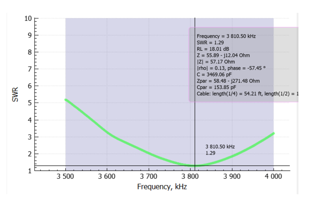
Figure 1: SWR curve for 80M EFHW
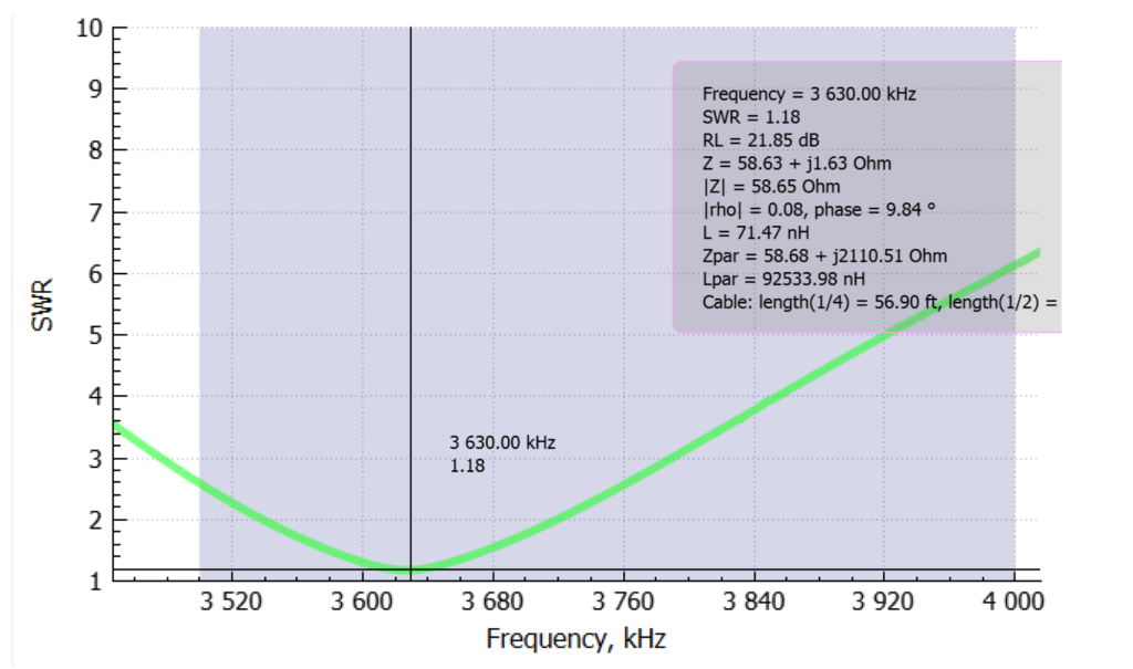
Figure 2: SWR curve for trimmed 80M Dipole
Figures 3 and 4 (page 4) show the new SWR curves with both antennas mounted on the tower sidearm and support trees. Those graphs show quite a different picture, especially for the EFHW. The EFHW graph has basically been inverted with the previous minimum SWR around 3.80 MHz replaced by a local maximum SWR at about 3.75 MHz. Changes to the dipole are less dramatic but also in a detrimental direction. The SWR minimum is now almost 2:1 instead of 1.18:1 and at a slightly higher frequency. The 3:1 bandwidth is much narrower at about 200kHZ instead of over 300 kHz. Based on these results, I took the EFHW down and left the dipole up to enable CW, digital and lower Extra voice operations on 80M with 60M capabilities as well.
After thinking about this some more, I decided to try the original idea of running the antennas perpendicular to each other. When I ran the antenna analyzer on the dipole (see Figure 5), I was encouraged that this was the answer. However, the EFHW behaved very strangely. No matter how much I changed the wire length, the SWR curve did not change! I suspected that maybe the balun was defective in some way and tried a different EFHW with the same results. At that point, I took the EFHW down again and decided to operate with only the 80M / 60M dipole.
I suspect that because the high impedance point is at the feedpoint and near the tower, that the tower is interacting with the EFHW in some way. To test this, I will have two ideas: 1.) reverse the antenna so that the feedpoint is at the end away from the tower (near the tree); and 2.) mount the antenna so that it runs directly away from the tower (not across two of the legs). These tests will be the subject of another article.
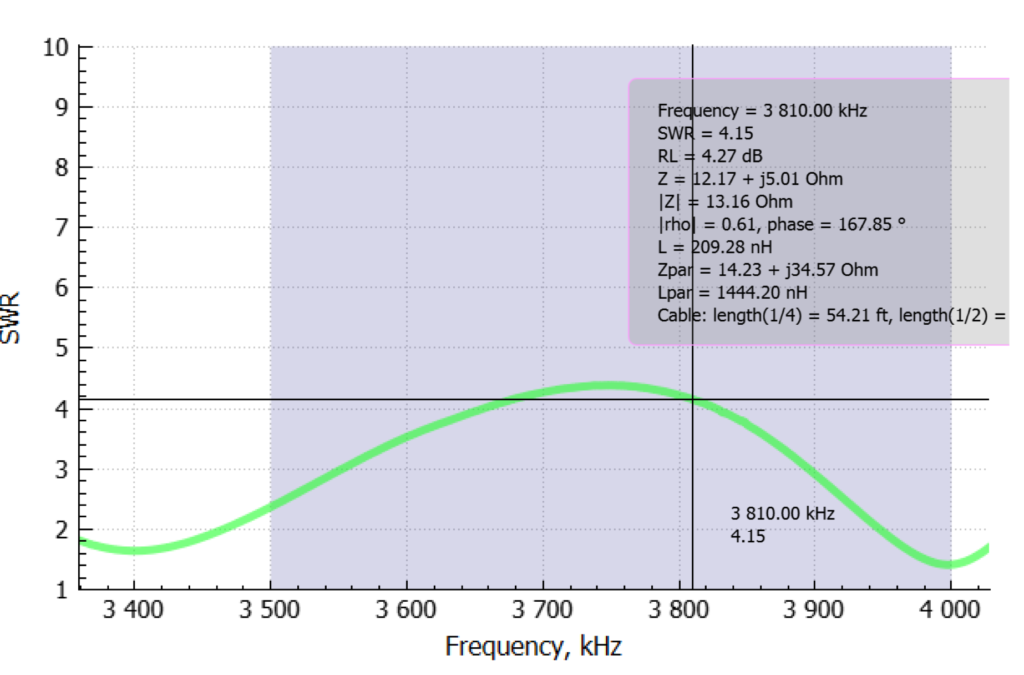
Figure 3: SWR curve for 80M EFHW mounted with 80M dipole
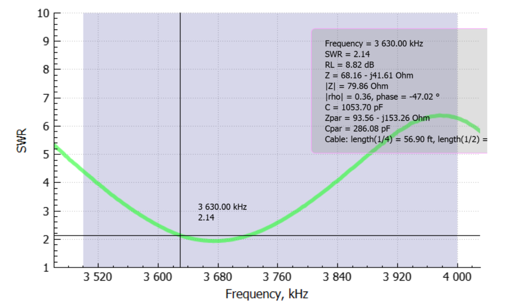
Figure 4: SWR curve for trimmed 80M Dipole mounted with 80M EFHW
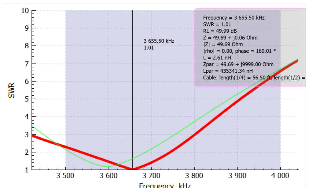
Figure 5: SWR curve for trimmed 80M Dipole mounted without 80M EFHW and with perpendicular 80M EFHW
Source PDF: 202402 – Antenna Interactions